Gfci Outlet With Switch Wiring Diagram
Each part should be placed and linked to other parts in particular way. If not, the arrangement won’t function as it should be.
Gfci Outlet With Switch Wiring Diagram Cadician's Blog
Any help would be great maybe a diagram can be emailed.

Gfci outlet with switch wiring diagram. Turn the power off and check the wire connections against the appropriate wiring diagram in step 7a or 7b. Wiring diagrams for ground fault circuit interrupter receptacles gfci electrical wiring home electrical wiring. Wiring a gfci outlet with a light switch diagram print the wiring diagram off plus use highlighters in order to trace the signal.
In the second wiring diagram, the lamp is connected directly to the line terminals of gfci (i.e. Led electrical services get free quotes from local pros. In the second diagram, the light switch is connected to the line terminals of gfci.
Replace the receptacle, screw it back into the box, and attach the cover plate. With this kind of an illustrative guide, you are going to have the ability to troubleshoot, avoid, and total your projects easily. Connect the line cables bare copper or green wire directly to the.
Receiving from point a to. Plug a clock radio or light into the outlet. This wiring diagram illustrates adding wiring for a light switch to control an existing wall outlet.
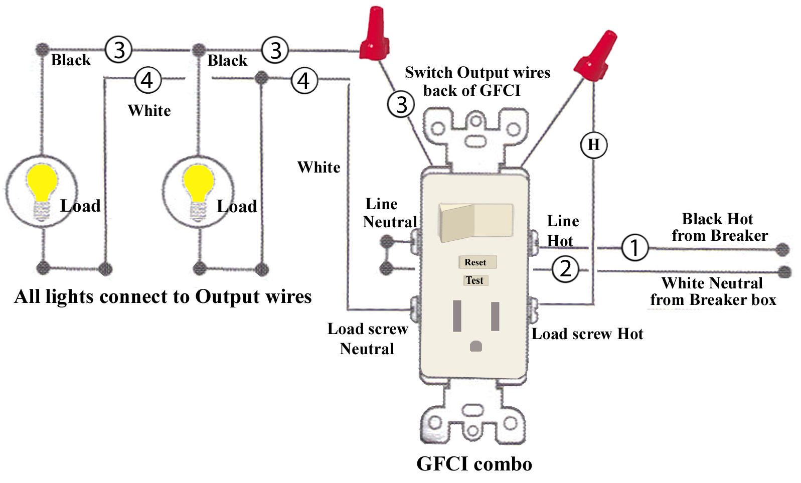
Gfci wiring diagram with switch. Wiring a gfci combo switch outlet with a light bulb in the first wiring diagram, the connected load (as light bulb) is gfci protected as it is control by the combo switch and connected to the load terminals of gfci. The neutral and ground wires are spliced together and run to each device in the circuit.
This way, the switch and light bulb is gfci protected. Gfci receptacle and switch same box electrical wiring home electrical wiring outlet wiring almost exactly what i need for the outdoor socket switch and light. Test the gfci by pressing the black “test” button on the outlet.
The hot source is spliced to the line terminal on the receptacle and to one terminal on the light switch. If more than 1 black and 1 white conductor are in the electrical box, also loosen the load side silver and brass terminal screws. This diagram illustrates wiring a gfci receptacle and light switch in the same outlet box a common arrangement in a bathroom with limited space.
At times the cables will cross. Wires that go into the line terminals are coming from a power source, for example your circuit breaker. Gfci electrical outlet wiring diagram.
( see diagram a ). The electrical wiring connections for the light fan and the gfci outlet will need to be identified in order to see if the gfci outlet can be wired to be on all the time. Wiring diagram for a switched gfci outlet outlet wiring gfci wiring outlets plug a clock radio or light into the outlet.
This diagram illustrates wiring a gfci receptacle and light switch in the same outlet box a common arrangement in a bathroom with limited space. This diagram illustrates wiring a gfci receptacle and light switch in the same outlet box, a common arrangement in a bathroom with limited space. Nancy october 21 2017 at 440 am.
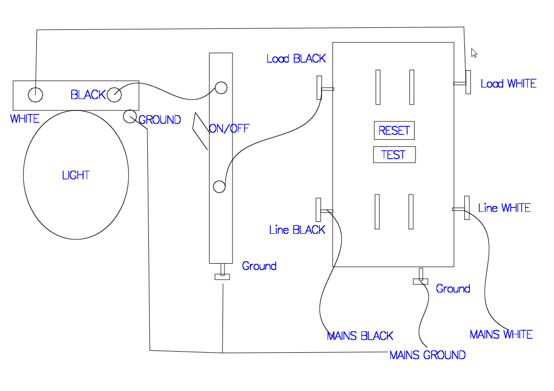
If more than 1 black and 1 white conductor are in the electrical box, also loosen the load side silver and brass terminal screws. • the black wire connects to the gfci hot lead. Light switch wiring diagram shows electrical power entering the ceiling light electrical box and then continues to a wall switch using a 3 conductor cable.
Each component ought to be placed and connected with other parts in particular way. Wiring a gfci outlet with a light switch in the first diagram, the single way switch and light bulb is connected to the load terminal of gfci. Switch with outlet wiring diagram.
In this gfci outlet wiring and installation diagram the combo switch outlet spst single way switch and ordinary outlet is connected to the load side of gfci. Gfci receptacle and switch same box electrical wiring home electrical wiring outlet wiring. Electrical panel wiring home electrical wiring electrical panel.
Plug a clock radio or light into the outlet. Gfci switch outlet wiring diagrams do a light off dual function afci leviton gfi combo problems installing how i connect to diagram for 20a with 15 amp smartlockpro combination wire 3 way electrical outlets and switches multiple circuit from seperate html switched half hot upgrading 2 g new install 4 wires receptacle methods replacing two. Outlets on same circuit diagram outlet wiring electrical wiring gfci.
Wiring a gfci outlet with diagrams do it for multiple receptacle electrical diagram and connection outlets diy what is where required how to install dengarden can t reset anko 20 amp ul listed leviton 125 volt combo self test technology thesamba com vanagon view topic 4 wires light circuit from ge 15 white dual function afci ground fault. Connect the bare ground wire to the green (ground) screw.
Wiring Diagram Of A Gfci Receptacle Popular How To Install

Leviton Presents How To Install A Combination Device With

Wiring A Gfci Outlet With A Light Switch Diagram
8 Popular Gfci To Switch Wiring Diagram Solutions Tone

120v Gfci Outlet Wiring Diagram Wiring Sample

Wiring A Gfci Outlet With A Light Switch Diagram Wiring
GFCI problem

gfci outlet wiring diagram Wiring Diagram and Schematics
Gfci Outlet with Switch Wiring Diagram Free Wiring Diagram

Wiring A Gfci Outlet With A Light Switch Diagram

Neutral Wire On Light Switch Nice Wiring Diagram, Gfci

Leviton Gfci Receptacle Wiring Diagram Free Wiring Diagram

120v Gfci Outlet Wiring Diagram Wiring Sample

electrical Existing GFCI outlet wiring to a new switch
120v Gfci Outlet Wiring Diagram Wiring Sample

GfciSchematicWiringDiagram RAUR.US

8 Popular Gfci To Switch Wiring Diagram Solutions Tone

gfci outlet wiring diagram Wiring Diagram and Schematics
120v Gfci Outlet Wiring Diagram Wiring Sample
